555 Timer Schematic / The 555 timer ic is an integrated circuit (chip) used in a variety of timer, delay, pulse generation, and oscillator applications.
555 Timer Schematic / The 555 timer ic is an integrated circuit (chip) used in a variety of timer, delay, pulse generation, and oscillator applications.. The 555 timer ic is an integrated circuit (chip) used in a variety of timer, delay, pulse generation, and oscillator applications. A resistor and a capacitor. 555 timer helpers schematic the addition of a capacitor to the trigger will not work for short output pulses as there is also a short delay in the recovery of the trigger terminal voltage. In this circuit, we will connect the 555 timer to be in astable mode. Jun 16, 2015 · the following figure is the schematic of ic 555 as a monostable multivibrator.
It was commercialized in 1972 by signetics. The basic 555 timer gets its name from the fact that there are three internally connected 5kω resistors which it uses to generate the two comparators reference voltages. The second 555 timer helper will extend the timers output duration without having to use large values of r1 and/or c1. I'm trying to design a 555 timer with duty cycle than 50% and, for some reason, it flashes once and then shines dimly continuously. The below figure is the schematic of a simple automatic on off timer with a fixed timing resistor and capacitor.
555 Timer Northwestern Mechatronics Wiki from hades.mech.northwestern.edu The 555 timer delay before turn off circuit we will build is shown below. In this circuit, we will connect the 555 timer to be in astable mode. In 2017, it was said over a billion 555 timers are pr. The below figure is the schematic of a simple automatic on off timer with a fixed timing resistor and capacitor. The 555 timer can be obtained very cheaply from pretty much any electronic retailer. This is the basic mode of operation of the ic 555. The 555 timer ic is a very cheap, popular and useful precision timing device which can act as either a simple timer to generate single pulses or long time delays, or as a. It produces pulses whose width can be varied.
In this circuit, we will connect the 555 timer to be in astable mode.
If you want to know all the pinout of the 555 timer, what each pin is and what each pin does, see 555 timer pinout. Jun 16, 2015 · the following figure is the schematic of ic 555 as a monostable multivibrator. It was commercialized in 1972 by signetics. Nov 03, 2018 · 555 timer here, 555 timer runs in free running mode i.e. In this circuit, we will connect the 555 timer to be in astable mode. This is the basic mode of operation of the ic 555. The basic 555 timer gets its name from the fact that there are three internally connected 5kω resistors which it uses to generate the two comparators reference voltages. The control input is used in some of the applications, but most of the applications the control input is not used hence the control voltage is equal to +2/3 vcc. The 555 timer ic is a very cheap, popular and useful precision timing device which can act as either a simple timer to generate single pulses or long time delays, or as a. In 2017, it was said over a billion 555 timers are pr. It requires only two extra components to make it work as a monostable multivibrator: 555 timer helpers schematic the addition of a capacitor to the trigger will not work for short output pulses as there is also a short delay in the recovery of the trigger terminal voltage. The 555 timer delay before turn off circuit we will build is shown below.
The 555 timer delay before turn off circuit we will build is shown below. It produces pulses whose width can be varied. Jun 16, 2015 · the following figure is the schematic of ic 555 as a monostable multivibrator. The 555 timer ic is an integrated circuit (chip) used in a variety of timer, delay, pulse generation, and oscillator applications. Jan 13, 2016 · hello.
555 Timer Tutorialspoint from www.tutorialspoint.com The first comparator has threshold input to pin 6 and control inputs for pin 5. The second 555 timer helper will extend the timers output duration without having to use large values of r1 and/or c1. The basic 555 timer gets its name from the fact that there are three internally connected 5kω resistors which it uses to generate the two comparators reference voltages. I'm aiming for a.2 sec pulse and 1.4 sec off. It requires only two extra components to make it work as a monostable multivibrator: Jun 16, 2015 · the following figure is the schematic of ic 555 as a monostable multivibrator. The 555 timer can be obtained very cheaply from pretty much any electronic retailer. It was commercialized in 1972 by signetics.
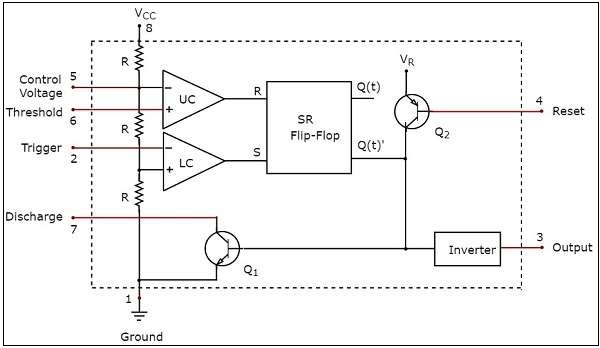
The first comparator has threshold input to pin 6 and control inputs for pin 5.
The basic 555 timer gets its name from the fact that there are three internally connected 5kω resistors which it uses to generate the two comparators reference voltages. A resistor and a capacitor. Derivatives provide two (556) or four (558) timing circuits in one package. I'm aiming for a.2 sec pulse and 1.4 sec off. Nov 03, 2018 · 555 timer here, 555 timer runs in free running mode i.e. This is the basic mode of operation of the ic 555. In this circuit, we will connect the 555 timer to be in astable mode. I've designed this in tina, but the circuit doesn't want to cooperate. Jul 24, 2019 · the working principle of the 555 timer is by considering the block diagram of the 555 timer ic. The control input is used in some of the applications, but most of the applications the control input is not used hence the control voltage is equal to +2/3 vcc. I'm trying to design a 555 timer with duty cycle than 50% and, for some reason, it flashes once and then shines dimly continuously. 555 timer ic (16) 8051. The 555 timer can be obtained very cheaply from pretty much any electronic retailer.
Jul 24, 2019 · the working principle of the 555 timer is by considering the block diagram of the 555 timer ic. The control input is used in some of the applications, but most of the applications the control input is not used hence the control voltage is equal to +2/3 vcc. The basic 555 timer gets its name from the fact that there are three internally connected 5kω resistors which it uses to generate the two comparators reference voltages. In this circuit, we will connect the 555 timer to be in astable mode. 4th pin is connected to vcc to avoid sudden resets.
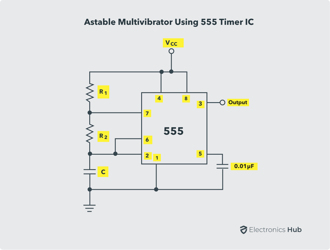
Astable Multivibrator Using 555 Timer Circuit Duty Cycle Applications from www.electronicshub.org I'm trying to design a 555 timer with duty cycle than 50% and, for some reason, it flashes once and then shines dimly continuously. The 555 timer ic is a very cheap, popular and useful precision timing device which can act as either a simple timer to generate single pulses or long time delays, or as a. So the time period after which this circuit will automatically turn on/off the output is fixed and can be found out by using the formula mentioned in the calculation section. I'm aiming for a.2 sec pulse and 1.4 sec off. Derivatives provide two (556) or four (558) timing circuits in one package. The breadboard schematic of the above circuit is shown below. I've designed this in tina, but the circuit doesn't want to cooperate. 4th pin is connected to vcc to avoid sudden resets.
In this circuit, we will connect the 555 timer to be in astable mode.
The first comparator has threshold input to pin 6 and control inputs for pin 5. So the time period after which this circuit will automatically turn on/off the output is fixed and can be found out by using the formula mentioned in the calculation section. 555 timer helpers schematic the addition of a capacitor to the trigger will not work for short output pulses as there is also a short delay in the recovery of the trigger terminal voltage. A resistor and a capacitor. In 2017, it was said over a billion 555 timers are pr. As the name specifies, a monostable multivibrator has only one stable state. Derivatives provide two (556) or four (558) timing circuits in one package. The 555 timer can be obtained very cheaply from pretty much any electronic retailer. The 555 timer ic is an integrated circuit (chip) used in a variety of timer, delay, pulse generation, and oscillator applications. Nov 03, 2018 · 555 timer here, 555 timer runs in free running mode i.e. It was commercialized in 1972 by signetics. I'm trying to design a 555 timer with duty cycle than 50% and, for some reason, it flashes once and then shines dimly continuously. Jul 24, 2019 · the working principle of the 555 timer is by considering the block diagram of the 555 timer ic.


0 Komentar